In this portion, I'm going to be covering my custom built base with the electronics to run my X-Wing starfighter. This is a stock photo of the base that comes with the kit. You can see it's a bit bulky and quite large where it connects to the underside of the X-wing.

I want a more slim and streamlined base for my X-wing. So I'm going to use this plastic storage container case I found a Joann's Linens. It's a nice hard solid plastic that should support the model just fine, and be easy to glue and attach my electronics too.


I will be using a 5/8" piece of PVC tube to hold the model itself.

So the first thing I've done is mark on the base where I'm going to attach my tube. Then I drilled it out at 5/8" for my tube to fit in. And it fits very nice and snug. Supports without any gluing, though I will glue anyway.


I removed the bottom support piece that plugs into the X-wing model so that I can figure out how to attach it to my tube.


So I've cut away a lot of the excess from the support portion and notched my tube to hold it in place.


So again, here is the kit base. I need the electronics and buttons that come with it to use in my custom base.

The first thing I'm going to do is remove the pin section at the top that plugs into the model so that I can use it on my base to attach my wire too.


With the pins removed, you can see how they fit inside the kit portion and attach in the model.


So my next step is to remove the neck of the kit base and all of the electronics from inside.


And what we have is the kit circuit board with wires and the kit speaker for the sound fx.

With the kit electronics removed, this is now everything I need to attach inside my custom base. We have...
Top left, Adafruit 3.3v Trinket, USB power board next to that, a latching switch just below, an Adafruit SoundFX mini board to the right of the switch, 2 momentary push buttons for my laser fire and random sound fx activation and finally the kit board.

To attach the boards to the base, I've cut small pieces of 1/8" tubing to use as standoffs and support the boards so they're not flush against the plastic.


I then placed the boards in the position I'd like them to be glued in and marked on the plastic where I need to cut away for USB access.


What this does, is give me access to plug in a USB cable to the Trinket or Sound board so I can update scripting or change sound fx if needed. And, of course, be able to plug in a USB cable to the power board to run the model itself.


I then drilled out a hole for the power button.


Next, I cut a small bread board down for an attachment for my 2 push buttons. I then soldered them into place.


I also removed the kit power switch from the kit board, as I won't be using it, and it also sticks out too much and prevents the board from sitting flush against my base. I then just soldered a jumper between to of the pins on the board so it's always hot. But it will not be active until my power switch is turned on.


Then holes were marked on the base in the proper position for the buttons and then drilled out.


At this point it's time to paint the base. First a coat of Tamiya gray primer, as always, then I used flat black Krylon paint and then gave it a coat of Tamiya clear gloss.


I further cut down the kit plastic plug in portion to as slim as possible to attach to my tube.

And cut a small notch on the side for a 3 wire plug to go through, as the 8 pin plug is not enough connections for all of the wires. The 3 wire plug will be hot and ground for my laser LEDs.

And then painted the PVC tube.

So with the base painted, it's time to permanently attach my electronics. I did this by hot gluing the board stand offs into position.


I am using some button caps to make larger activation buttons, which will push against the board buttons. So I put the button caps into position, then glued the remaining boards over them.


Attaching the speakers for sound is my next step. I decided for the kit speaker to use the enclosure that came with the kit. So I marked it out from the kit base and cut it out and removed it.

I then glued the enclosure to my base and mounted the speaker inside.


Time to solder all of my wires for the electronics. All of the power and trigger wires.


I also have an additional speaker to use for my sound fx for the laser fire and just random fx. I also wanted a speaker enclosure for mine as well, and found that a Coke bottle cap was the perfect size for the enclosure. So I cut some slats in the bottle cap for sound to come through, used the speaker's self adhesive tape to attach it to the coke bottle cap, then glued the cap onto my base.


With everything in place, and a quick test, I'd like the sound to be a little better. Because the base sits completely flush against a tabletop, I notched all 4 sides of the base slightly for the sound to be better heard.

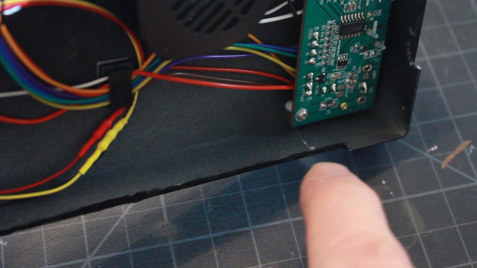

I then ran all of the wires through my PVC tube and glued it into position on the base.


And here we have the complete inside of my base wired up, secured and ready to go.

The next step is to solder the wires to the appropriate pins. So I hot glued the pins into the pin housing that plugs into the model, then soldered the wires.


With the pin section soldered up and ready, I then hot glued the pin housing into my PVC tube, and left my 3 pin plug running out the notch on the side to plug in my laser LEDs.


And here we have my completed base. When attaching, the 3 pin plug is plugged in to the plug hanging from the bottom of the X-wing, which is then inserted inside the small side notch, as to conceal, then the pins are plugged into the model.

And a test fitting of the model in place. Though I did not slide the 3 wire plug into the notch at this time. This was purely for a test fitting and to fire it all up and make sure everything works. And everything did work just fine. The engines and cockpit light, the torpedoes fire, the lasers fire, the wings open and close, and the random sound fx play as well.


So in my next post, and probably my last, I will be doing final weathering and painting of this beautiful X-wing model
So stay tuned. Much more to come...
Hi, Chris.
ReplyDeleteI was so impressed by this, I wanted to do something very similar. I have obtained the kit, but wonder how you achieved the electronics aspect. Have you documented that part anywhere in any greater detail, or can you suggest where I can get some knowledge around this?
Many thanks, for both the videos and Photos. Your build are really nice.
Kind regards, Chris Gold (UK)
This blog I did and my YouTube videos are all I've done. I just did a bunch of research myself online to learn how to do a code sketch. As for LEDs, I've been doing that for a bit now, and just started out with experimenting and again, online videos and forums. For my X-wing, I just jumped in hoping for the best. I spent a good amount of time with a meter checking all the connections on the kit motor and how the buttons worked and just kept testing till I knew exactly how it was working so I could incorporate my electronics with it.
ReplyDelete