So in this part, I'll be running my engine LED wiring and laser canon LED wiring into the kit motor housing. This will get me to a point where I can finally start to assemble the fuselage of the X-Wing model. So let's get to it.
I have the motor housing opened up here.

The first thing I've done is unsolder 2 points where the kit cockpit LED connects to the motor board, and I remove the cockpit LED.


My next step is to make my 4 engine LEDs, using Adafruit 3030 Neopixels.


This is the backside of the LED, where I have to solder my positive, ground and data pin wires to.


And a little test of how the LED will look through the engine of the X-Wing.

So I've soldered all 4 of my engine LEDs with the appropriate wires and put some shrink wrap on the ends to help keep them a little stiff where they slide into the kit engine housing.


And a test of the LEDs to make sure they're all secure and soldered well.

You can see in the following photos, the kit engine LED slides into this engine housing and seats against a rim and the tip of the LED just lays flush with the outer edge of the housing.


While my neopixel LED fits inside the housing, the ridge inside keeps it from protruding all the way to the edge of the housing. In fact, it's set back quite a bit.


To remedy this situation, I drill through the center of the engine housing and remove the ridge so my neopixel LED can go all the way through a lay flush with the edge of the housing.


Now I have that out of the way. I'm going forward in the instructions to see how it all fits together to head off any problems I may have later. I don't want to have to deal with these things once my LEDs are soldered in place in motor housing.
So my next step is to remove one of the kit engine LEDs from the motor housing. There's a little clip on the s-foil that holds the wires in place and conceals them from site when the model is assembled. So I just have to unsnap this little clip to remove the wire.


So, looking forward in the instructions again, the LED has to go through this little section of the engine. My neopixel LED is to large to fit through the one end of this piece.


But I can run my wires through the opposite end. The problem with this is I can't do this once the wires are soldered to the motor housing board. So I'm going to have to solder my wires to the board with this model section already in place.
Again, looking forward, I can see there's just a bit of this piece that will be seen in the completed model. So it will need to be painted.

So I've painted these pieces with Tamiya gray primer and then a coat of my body color, Tamiya AS-20 Insignia White.

I cut a loose piece of wire that the same length as the engine LED wire that comes from the motor housing.

In doing this, I can line the wire up against my engine LED and mark the point at which it physically enters the motor housing. This will then give my the correct length, so that when the engine is assembled, my LED will sit flush with the end of the housing piece that I drilled out earlier.


So I then run all 4 of my engine LEDs through the one engine piece...


run them into the motor housing and seal them back up with the clip on the s-foils.


And all 4 engine LEDs have been run into the motor housing.

To remove the kit engine LEDs, I removed this portion of the kit board where they were all soldered to. I will not be needing or using this in my build.

Instead, my engine LEDs will be soldered directly to the main board for their power and data pin.

Here I have the ground wires, positive wires and date pin wires all soldered together. At this point, I'm also inserting the connector which will power the cockpit LEDs. This connector will be soldered to the kit board as well for it's power.

These wires are then soldered to the main board in the appropriate area. Ground and hot will be using the same solder connections as the kit electronics, and my white data pin cable is soldered to pin #2 of the main board, which is unused by kit.

And a quick test of the engines after being soldered to the board.

So the last bit I need to do to the motor housing is run my laser canon LEDs into it and solder them in place. I am using 0402 SMD red LEDs for my laser canons on the wings.

This 3 pin 2.5mm JST connector is what I will be using to power and run my laser canon LEDs. The ground wire for all 4 LEDs, and then the yellow wire for 2 of the LED's hot and the red wire for the other 2 LED's hot.


Before I can run my laser canon LEDs into the motor housing, I once again am going forward in the instructions to see how it all assembles, as not to hose myself later in the build. I'm also doing this to check my length of wire on the LEDs.
So the laser LED will come from the motor housing along side the engine wires and then run into the wings.


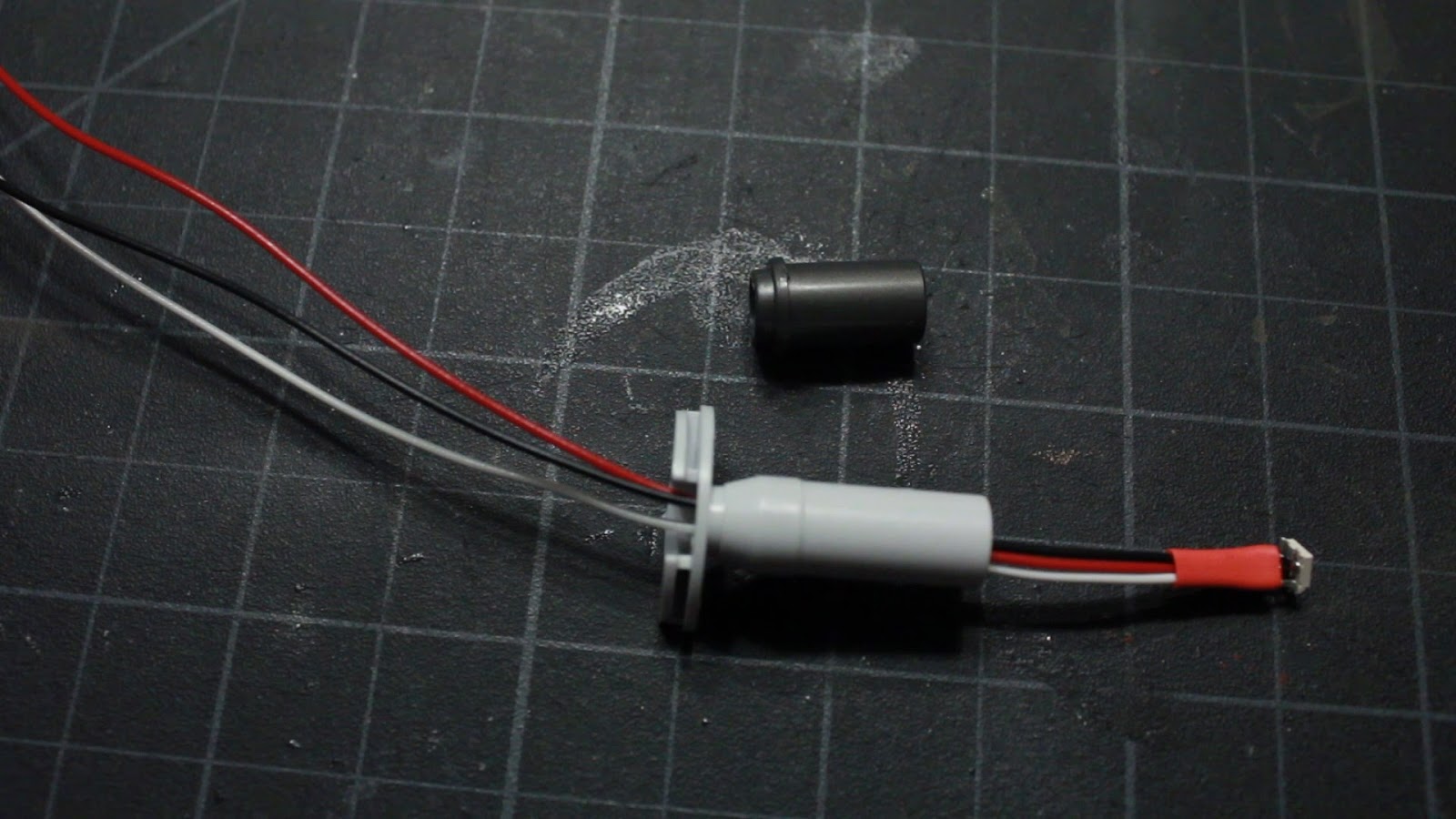
At the tip of the wings, is where the laser canon housing goes. It slides on in place on the tip.

And you can see here there's a little piece that sticks up on the wing that will be the perfect spot for my wires to run through and be concealed.

I've cut out a little section of the end of the laser canon housing....

cut out a little trench area for the LED wires....

and cut a little snip out of the bottom of the laser canon housing for the LED wires to come through from the wings.

And the LED wires will fit inside the laser canon housing like so.


You can see when the laser canon housing is attached to the end of the wing, the wire is completely concealed by that little section of the wing that sticks up. It looks great.


Then the wires will run along the inside of the wings to the motor housing.

So now that I know it will all work OK, it's time to run my laser canon LED wires into the motor housing, right along side the engine wires and under the clips.


So all 4 LEDs have been run into the motor housing and I need to solder the ground wires together and attach to the ground pin of my 3 pin connector. The 2 of the LED hot wires to the red wire and the other 2 LED hot wires to the yellow wire of the 3 wire connector.


Then a quick test of the LEDs to make sure the solder is good and all the wiring is good.

So now that everything is working great, the engine LEDs, the laser canon LEDs, and the cockpit LEDs, tested in the previous blog, it's time to finally button up the motor housing for good. So my 3 wire connector is run through the opening along side the kit connector for the base.


And here we have the completed housing. Everything soldered in place inside and working.

So now that this whole assembly is done, I can finally move on to doing the fuselage and body of the X-Wing. Now is when it will finally begin taking shape. So my next post will be working on the fuselage and assembling with the cockpit and motor housing.
So stay tuned. Much more to come...